

During a recent cargo audit, I asked a duty officer a simple question. “The checklist asks whether the electrical insulation of the interface is effective. What exactly have we checked?” The answer came back with total confidence: “Bonding is checked.”
That answer revealed the gap. It is the same inspection weakness discussed earlier in SIRE 2.0: Digital Ambition Crashing into Analog Ineptitude: a checklist only works when the person using it understands the operational intent behind the question.
The checklist wasn’t asking if a wire had been clamped to the hull. It was asking if the electrical insulation barrier at the transfer interface was intact. By treating “bonding” and “insulation” as interchangeable terms, that officer fundamentally inverted the safety logic of the entire operation.
In ISGOTT 6, the ship-shore safety checklist is explicit: “Electrical insulation of the tanker/terminal interface is effective.” In the latest Ship-to-Ship (STS) transfer protocols, item CL 4A, No. 10 demands the exact same thing: “Electrical insulation of the ship/ship interface is effective.”
Those words are deliberate. Yet onboard, bonding, grounding, earthing, insulation, and continuity are routinely tossed around as if they mean the same thing. They are entirely different safety barriers designed to combat entirely different physical hazards.
The Cost of a Loose Definition: Tanker Disasters
Confusing these controls can have fatal consequences. The cases below show how isolated conductors and uncontrolled static charge can become ignition sources, while MT Pablo shows how much may remain unknown after a catastrophic tanker explosion.
- The Insulated Float, Okayama, 1985: A chemical tanker loading benzene exploded after a Teflon ring, fitted to reduce noise from the level gauge, electrically isolated the metal float from the ship’s structure. Static charge accumulated on the float and discharged to the guide pipe, igniting the benzene vapour inside the tank.
- The Ungrounded Probe, MT Fiona, 1988: FIONA’s No. 1 cargo tank exploded while a surveyor was measuring the cargo temperature before discharge. Leaking steam had generated static charge inside the tank. The charge accumulated on an ungrounded temperature probe and discharged as the probe was withdrawn, igniting the flammable atmosphere. The surveyor was killed.
- MT Pablo, 2023: MT Pablo exploded while in ballast off Malaysia, ripping open much of the cargo deck. Of the 28 crew members, 25 survived, four with serious injuries, while three remained missing and were presumed dead. The precise cause was never publicly established. Residual hydrocarbon vapour inside the cargo tanks has been widely suspected, with static or electrical discharge discussed within tanker circles as a possible ignition source.

Current Needs a Path
Electric current needs a path.
During ship-shore or ship-to-ship transfer, two large steel structures may not be at the same electrical potential. One ship may have impressed current cathodic protection, another may have sacrificial anodes, and a terminal may have its own cathodic protection system with its own stray currents.
If a conductive path joins the two sides, current can flow through that path as the potential difference reduces. That path may be a hose fitting, flange, bonding cable, crane wire, gangway, vapour line, hose saddle, wire sling or improvised support. If the path is made, broken, or disturbed in a hazardous vapour area, sparking or arcing can occur.
This is why a manifold check alone is too narrow. An insulating flange can be bypassed by metallic hose supports. Ladders, gangways, crane wires, hooks and fender cages may also create unintended electrical paths between the ships.
SIGTTO explains the purpose of insulation flanges and electrically discontinuous hoses at ship-shore and ship-ship interfaces: they protect against ignition caused by arcing.
The real control is keeping current out of unintended paths at the cargo interface.

Static Electricity Is a Separate Risk
Static electricity within the cargo system and electrical potential difference between two ships are separate hazards requiring different controls.
Movement of low-conductivity cargo can generate static charge, particularly during high flow rates, splashing or free fall. Because the cargo dissipates charge slowly, charge may remain within the liquid or accumulate on isolated conductive equipment. Tank washing and steam leakage can also produce electrically charged mist.
Within each ship, cargo pipelines, reducers and other conductive components must therefore maintain electrical continuity. Bonding leads across gasketed flanges prevent an isolated section from accumulating charge. Sampling, ullaging and temperature-measuring equipment must also be properly bonded before introduction and remain bonded until it is withdrawn. This keeps the equipment at the same electrical potential as the ship and prevents accumulated charge from being released as a spark. Bonding does not, however, immediately remove charge retained within the cargo or mist, so the required relaxation period and operating precautions still apply.
At the transfer interface, the requirement is different. An insulating flange or electrically discontinuous hose prevents current caused by the potential difference between two ships from passing through the cargo hoses.
The same operation therefore requires bonding within each ship and electrical isolation between the ships. That is why “bonding is connected” is not a complete answer. The real questions are: what has been bonded, and where has electrical isolation been maintained?

Master the Vocabulary
The problem is rarely the word itself. The problem is using the wrong word at the wrong barrier.
At the manifold, these terms are not academic. They decide whether the operation is trying to connect, drain, separate, prove continuity, or prove an electrical break.

Bonding Cable Is Not Always Safety
A bonding cable looks like a safety measure. That is why it can be misleading.
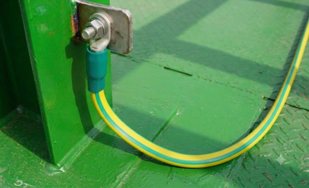
At many terminals, the bonding cable is a shore-supplied cable connected to a metallic point on the ship. It gives the impression that the safest arrangement is always to connect ship and shore electrically.
At tanker transfer interfaces, that is not always the safety logic. The approved protection is often electrical discontinuity, provided by an insulating flange or an electrically discontinuous hose. The purpose is to prevent ship-shore or ship-ship current from using the cargo transfer arrangement as its path.
Reading this as a maritime insider, seafarer, or enthusiast?
Subscribe to The DeepDraft for maritime analysis, daily SITREP updates, weekly briefings, and operational signals worth watching.
SIGTTO records why the practice changed. Research in the 1960s and 70s concluded that bonding wires provided no protection against low-voltage stray currents and could themselves become a source of ignition. By the second edition of ISGOTT, insulating flanges had become the accepted protection against low-voltage arcing at ship-shore transfer systems.
If a bonding wire is still required by national or local regulation, it must be treated as a controlled connection, not a substitute for isolation. It should be connected outside the cargo or bunkering area, through a switch in an Ex enclosure, closed only after proper attachment and opened before disconnection.
The question is simple: does the actual deck arrangement preserve the approved electrical arrangement?
The ICCP Dilemma
ICCP protects the hull from corrosion by applying controlled current to the underwater structure. During STS, it becomes relevant because two steel hulls may not sit at the same electrical potential. If a metal path connects them, current can pass from one hull to the other. The cargo hose, manifold, bonding lead, crane wire or hose support can then become part of the circuit.
The common mistake is treating ICCP as a switch that must automatically be turned off before cargo transfer. That is not the logic of the latest STS guidance. The 2025 STS Guide does not treat ICCP status as a simple on-or-off checklist decision. Section 4.13 states that positive physical isolation via an insulating flange or discontinuous hose remains your primary control.
The first control is still the physical electrical barrier. If the ships are positively isolated by an approved insulating flange or electrically discontinuous hose, that isolation remains the primary protection. In that condition, ICCP is normally left running unless local rules, maker guidance or the risk assessment require otherwise.
Even where positive isolation cannot be fully confirmed, switching ICCP off by habit is not automatically safer. If both ships have healthy ICCP systems, the STS guidance indicates they are generally best left running to reduce the potential difference between the hulls.
The caution comes when the system is no longer balanced. If one ICCP system has failed, or one vessel has no cathodic protection, switching off the working ICCP may need to be considered before the ships come together. Some ports and terminals may also require cathodic protection systems to be switched off.
So the practical position is clear:
Do not switch ICCP off by reflex. Confirm the isolation barrier, confirm the condition of both cathodic protection systems, and then follow the STS guidance, local rules and risk assessment.

What the Vessel Should Actually Check
Before hose connection, the cargo team should identify the intended electrical arrangement.
Where is the insulation barrier? Is it an insulating flange, an electrically discontinuous hose, or a semi-continuous hose arrangement? Is bonding required by terminal instruction, local regulation or STS guidance? Does the vapour return line follow the same electrical logic?
Then comes the deck check. The arrangement must not be bypassed by the support system around it. The 2025 STS Guide warns that where an insulating flange is used, no conducting hose section outboard of that flange should contact the ship to which the flange is fitted, including through non-insulated hose saddles. It also identifies other possible arcing points such as metal ladders, crane runners, hooks and fender cages.
That is the real audit point. The flange may be correct. The hose may be certified. The deck may still defeat both.
If the certificate says one thing and the deck arrangement assumes another, the barrier exists only on paper. That paper-versus-reality gap is the same trap covered in Crude Oil Washing Records in ORB Part II: A MARPOL Compliance Trap, where a record may look clean while still failing to describe the actual operation.
The Tool
The following tool is for operational understanding only. It does not replace ISGOTT, the STS Guide, terminal instructions, local regulations, company procedures, maker guidance, POAC advice or the Master’s risk assessment.
Its purpose is to test whether the electrical logic of the operation is being understood correctly.
Practical ICCP & Cargo Transfer Logic Tool
Operational understanding only. This does not approve cargo transfer and does not replace ISGOTT, the STS Guide, terminal instructions, local regulations, company procedures, maker guidance, POAC advice, or the Master’s risk assessment.
1. Operation and Interface
2. Deck Bypass Check
3. Certificates and Local Requirements
4. ICCP / Cathodic Protection
Use note: the safe answer is not generically “ICCP On” or “ICCP Off.” The first question is whether the cargo transfer interface is electrically controlled and whether that control is preserved on deck.
The question remains the same in every case. Is the interface positively isolated, and does the bonding, hose and ICCP arrangement support that isolation?
DeepDraft View
ISGOTT Item 54 and STS CL 4A, No. 10 ask the same operational question: Is the electrical insulation of the interface effective?
A checklist is an operational necessity, but a ticked box carries zero physical protection. It only proves a pen touched paper. It does not prove that the duty officer walked the deck to ensure a steel gangway or a crane wire isn’t accidentally bridging the insulating flange. It does not prove that the hose hooked up matches the electrical properties stated on the certificate.
Before a single manifold valve is opened, the cargo team must be able to trace the deck arrangement and explain the barrier in plain words: Where is current allowed to flow? Where is it forcibly stopped? What on this deck could accidentally bridge that gap?
Media Section
Sources Reviewed
ISGOTT 6
Ship to Ship Transfer Guide 2025
SIGTTO
46 CFR Part 35, Subpart 35.35
Transport Canada Ship Safety Bulletin No. 17/1998



Leave a Reply